Computer Numerical Control milling, or CNC milling, is a machining process employing computerized controls and rotating multipoint cutting tools to meticulously eliminate material from the workpiece and create a custom-built product or part.
The process is perfect for machining a variety of materials, including metal, glass, wood, and plastic, and developing various custom-designed products or parts. Several functionalities are enabled under the umbrella of precision CNC milling.
With precision 3-, 4- and 5-axis CNC machining centers equipped with other advanced capabilities, companies can now handle all your CNC milling projects smoothly, allowing you to focus on bringing your product or service to the market. Here’s everything you need to know about CNC milling and how it’s shaping the industry for better.
IMAGE: PEXELS
CNC Milling – Explained
CNC milling, similar to other subtractive forms of manufacturing, serves to eliminate the material to develop a robust design. The milling process comprises multipoint cutting tools being regulated by a computerized program that reads and translates the machine paths, which originate from CAM/CAD software (Computer-aided manufacture or design) programs used to build an automated design of the product.
Milling Machine Programming
CNC machining works via a machine reading instructions from the design inputted on a CAD program. These designs can either be two or three-dimensional. Once completed, these designs are then transformed into a machine-based format.
After that, CAM software exports the machine-readable format to a CNC machine program that acts as instructions for directing each move the machine will be making to replicate CAD design with the preferred material.
Milling Machine Setup
Before undergoing the manufacturing process, the machine must be set up using proper CNC machining tools. The operator must also put the workpiece on focus and fix it in place using custom fixtures and jigs.
These are essential steps. They help ensure the machine can carry out the job required without the material spreading everywhere. When the necessary preparations are done, the operator will launch a program via the machine interface, enabling the manufacturing process to start.
Milling In Action
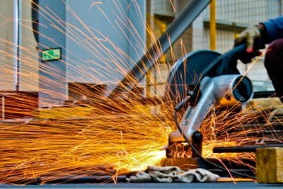
As the manufacturing starts, the CNC tools may spin at 1000+ RPM, and therefore, may cut into the most robust materials effortlessly. During this manufacturing process, the workpiece and tool will be transformed in regard to each other to access various parts of the build. The direction and angles depend on the specific design requirements of the workpiece, but the idea of feeding the piece to the rotary tool remains equivalent.
Types Of CNC Milling
Slab or surface milling, commonly known as plain milling, involves implementing a cutting tool, the rotary axis of which is identical to the surface of the material. Therefore, it’s often called surface milling, used to design a flat surface on a product or part.
When it comes to face milling, the rotary axis tends to be perpendicular to the material’s surface. Unlike plain milling, the tools for this milling have more teeth. The teeth you’ll see on the edge of the cutting tool are principally used for cutting, while the teeth close to the flat material are great for finishing touches.
As the name indicates, angular milling involves the tool’s rotary axis being at an angle to the surface of the workpiece; rather than parallel or perpendicular; these machines basically cover the angles in between.
Then there’s form milling, used for products or parts with no flat surface. These machines are often used for materials with contours and curves utilizing specialized tools based on the curve type.
Usually, superficial surface cuts are carried out via larger cutters. On the other hand, a more narrow cutter may be used for finer details. Larger amounts of material are initially eliminated using a coarse-toothed tool. After that, a faster, smoother, more fine-toothed cutter can be used for the more comprehensive parts of the build, as well as for finishing.
The Anatomy Of A CNC Mill
For you to understand how exactly a CNC Milling machine works, you need to take a look at the list of the key parts a CNC mill comprises. Therefore, we have compiled a brief list of the parts in use:
- Worktable – the place where you secure the material and begin the process on
- Saddle – placed right below the worktable for support; it is adjustable so you can fix the worktable based on the spindle axis
- Knee – just under the saddle, a knee is what supports the saddle and worktable and saddle; it is often moved up and down based on whatever height is required
- Column – the fixed base of the CNC machine that can also house stuff like coolant, machine oil, etc.
- Spindle – this particular component is driven via a motor inside the column that supports it; a spindle controls the machine tool
- Mill cutter – often referred to as a machine tool, this equipment touches and eliminates parts from the piece and may vary in type based on the job required, such as a cutter, bore, drill, and so on
- Arbor – the arbor practically connects the machine tool to the spindle
Wrapping Up
Explained above are the basics of the CNC milling, various milling operations, and their equipment. As you can see, CNC mills can function on various materials, including plastics, wood, metals, and even glass.
These milling machines are often programmed to work at a wide variety of depths and angles. They have the ability to function on large, heavy workpieces, which makes them a versatile machine. If you have any questions regarding the CNC milling process, feel free to share your thoughts with us in the comments below.
If you are interested in even more technology-related articles and information from us here at Bit Rebels, then we have a lot to choose from.


COMMENTS