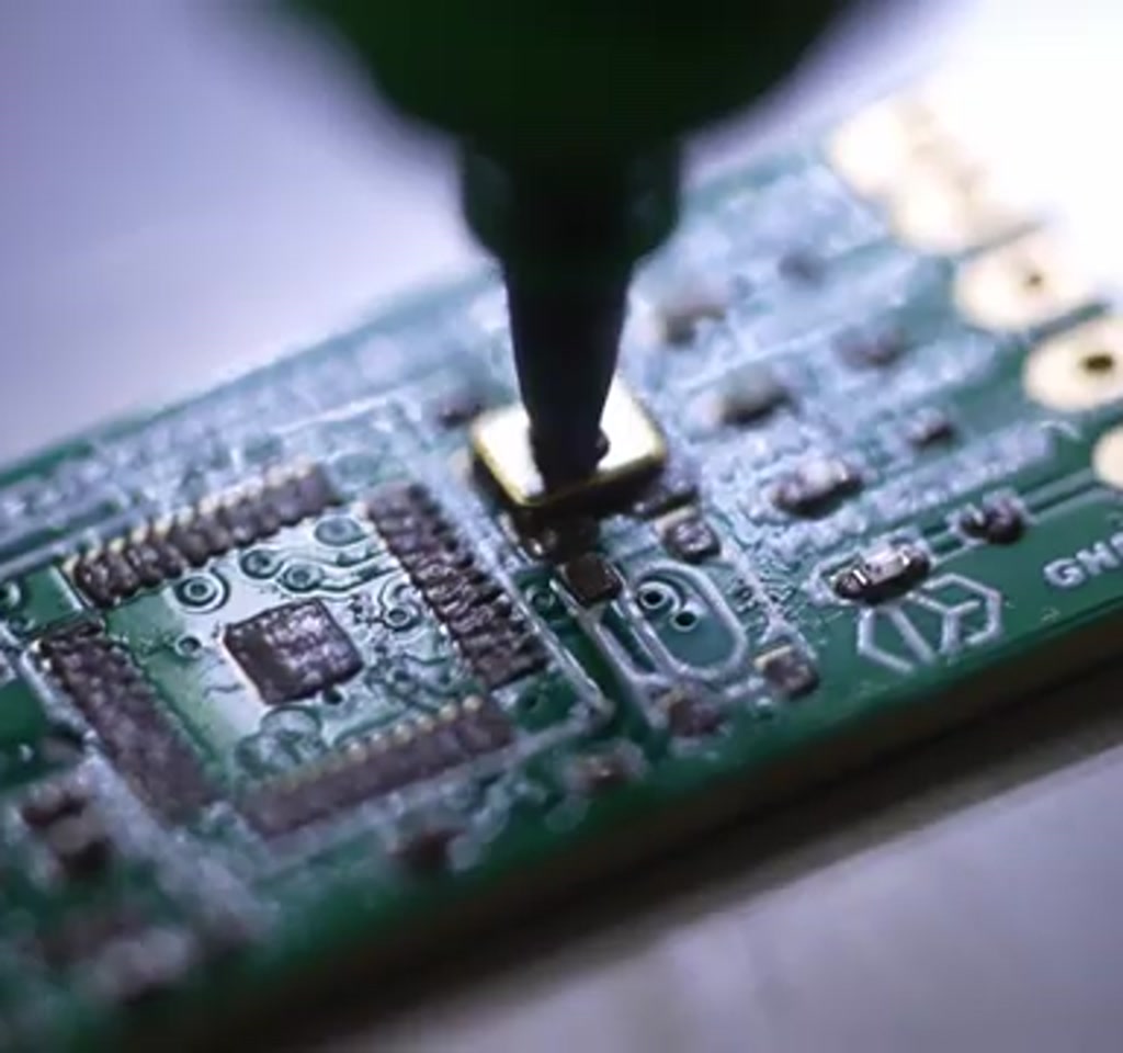
Handling a 0201 component is not an exaggeration about dexterity. A 0201 is roughly 0.6 by 0.3 millimeters, a dot that lives in a world where human fingers and tweezers begin to feel like blunt instruments.
The standard reaction is that this scale requires factory floors full of million-dollar machines. The surprising claim from a recent build is different: with careful mechanical choices, a stripped-down controller and human analog control, a benchtop pick-and-place machine can reliably handle 0201s while staying near a $200 parts budget.
The real significance here is not only the sticker price. What actually determines whether this matters is the combination of two things. First, a mechanical design that trades speed for repeatable micron-scale movement. Second, an interface that accepts manual pacing rather than trying to mimic industrial throughput. That pairing turns what looks impossible into a usable, if deliberate, workflow.
Most people misunderstand what the cost target changes. Cheap does not mean crude. The cost constraint forces different engineering decisions, and those decisions reveal the true tradeoffs: precise, slow placement versus fast, expensive automation; openness and repairability versus sealed black box reliability.
One clear result is cultural: when precision is divorced from six-figure budgets, independent makers can attempt denser boards and more advanced modules without a production line. That possibility is the tension this project explores and the reason its details matter beyond the parts list.
Why 0201s Are The Gatekeepers Of Modern Hobby PCB Work
Surface mount technology has been shrinking for decades, and the 0201 is where hand assembly visibly becomes painful. At 0.6 by 0.3 millimeters, these components are far smaller than a grain of rice, and any misalignment of an IC with tight-pitch pins can be catastrophic on a populated board.
Industrial pick and place machines solve this with high-speed vision systems, precision feeders and mechanical repeatability measured in microns. Those systems are expensive to buy and to operate. The question the maker asked is practical: can the same precision in placement be approached by dramatically cheaper hardware if the workflow accepts human-in-the-loop pacing?
What Is A Pick And Place Machine?
A pick and place machine is a device that automatically picks electronic components from a supply, aligns them and places them on a PCB. For hobby and benchtop systems the definition expands to include semi-automated rigs where a human operator controls timing and alignment while the machine provides mechanical repeatability and fine motion.
How This $200 Pick And Place Works
The build trades speed for repeatability: mechanical reduction through M3 threaded rods, friction-managed printed gears and a human-paced control scheme. Motion is deliberate and micro-stepped, vacuum picks components and the operator sequences placements rather than a camera-guided autonomous loop.
Making Microns With Cheap Hardware
One of the clearest engineering moves in the build is to accept slower linear motion in exchange for step-size precision. Belts and rack and pinion are great for speed. They introduce backlash and relatively large steps for micrometer work. The alternative chosen here is the humble threaded rod.
There are two lead screw stories to keep in mind. Standard 3D printer lead screws can move many millimeters per revolution. For example, an 8 millimeter per revolution style with 200 full steps per motor gives about 0.04 millimeters, or 40 microns, per step. That is fine for many applications but not for 0201 placement.
Using an M3 threaded rod changes the scale. An M3 thread has a 0.5 millimeter pitch, which with a 200 step motor yields 0.0025 millimeters per step, or 2.5 microns per full step. To be realistic about mechanical tolerances, the maker adopted a safety factor and quoted a practical control resolution near 10 microns. That figure is useful because it establishes a quantitative boundary: placement precision that often falls within single-digit tens of microns.
Backlash, Preload And Mechanical Tricks
Backlash is not magically solved by using threaded rods. The design reduces it by using two nuts in slight compression so the thread contact is effectively preloaded. The concept is simple and cheap but it has limits. Preload reduces play but increases friction, so motor torque, wear and motor current become part of the tradeoff.
Another clever mechanical choice is the use of printed herringbone gears. These gears were printed with near zero clearance then lapped together with an abrasive compound until the surfaces matched perfectly. The resulting meshing was described as buttery smooth, a tactile detail that matters because smooth contact reduces microslips and vibration that would otherwise defeat the fine control from the screw drives.
Controls And The Analog-To-Digital Turning Point
The maker started with a commitment to analog control. Two joysticks were chosen to map human intention directly to motion: one controlling X and Y, the other controlling Z and rotation. The joystick press toggled a vacuum. The original aim was to make speed an analog function of joystick deflection so small movements produced tiny steps and full deflection triggered higher pulse rates.
Analog control is elegant in principle, but the electronics needed for a robust, drift-free scheme are not trivial. Deadzones and direction thresholds are necessary because joysticks are not perfectly centered. The initial analog plan involved comparators, deadzone circuitry, and a 555 configured as a voltage-controlled oscillator to turn the joystick voltage into pulses for the stepper driver.
Why The Digital Switch Matters
After attempts to make that work in analog hardware, the maker switched to a microcontroller-based digital approach. The board chosen for the control brain was an ESP32 module in a Nano footprint and, in a pragmatic stroke, the mainboard of an Ultimaker 3D printer was repurposed since it already exposed multiple stepper driver slots and a compatible microcontroller architecture.
Going digital simplified generating very high frequency step pulses and allowed the implementation of deadzones, acceleration curves and variable speed mapping in software instead of analog circuits. That choice shifts some complexity from the physical wiring into firmware. For the maker, it also unlocked higher pulse rates for the steppers, which matter when attempting micro movements with no mechanical reduction aside from thread pitch.
That choice has a cost: debugging firmware and managing driver reliability becomes central. In this build the maker experienced intermittent failures from a stepper driver that would randomly overheat and die. The machine could be made to work with fewer motors, but driver reliability became an explicit constraint on deployment and sustained use.
Benefits And Practical Advantages
A low-cost pick and place delivers precise placement for prototypes and small runs without expensive feeders or full camera alignment. It enables single-operator workflows, supports boards when source files are missing and reduces the setup overhead that makes quick experiments costly with industrial gear.
Constraints, Limitations And Tradeoffs
The tradeoffs are explicit: throughput is measured in tens to low hundreds of parts per hour rather than thousands, maintenance is higher, and reflow remains a separate failure mode. Soldering profiles and component heat sensitivity still govern yield independently of placement precision.
Build Choices, Cost And Quantified Constraints
A constraint that grounds the whole project is money. The mechanical frame, rails, and a mix of FDM and resin-printed parts were kept intentionally low cost. The parts tally for the gantry, guides and printed elements came in just under $180, with a practical end figure near $190 to $195 when accounting for all printed plastics and small sundries.
- Precision Versus Throughput: Industry machines place components in fractions of a second and can do thousands to tens of thousands of placements per hour. This benchtop approach trades that speed for placement measured in dozens of seconds per component. A reasonable estimate is tens to low hundreds of parts per hour, not thousands.
- Cost Versus Reliability: By repurposing an open 3D printer mainboard, using inexpensive motors and printed gears, the upfront cost drops into the low hundreds. That choice introduces reliability constraints. Expect driver failures, the occasional misprint requiring part reprints and vacuum pumps that need selection and testing.
There are secondary quantified realities to watch for. Soldering temperature is not forgiving for tiny packages. The maker noted that a recommended soldering profile centers near 240 degrees Celsius for the board used, and an accidental overshoot of around 100 degrees can damage components. That fact changes risk calculus: a cheap pick and place reduces placement error, but reflow control remains a separate and measurable source of failure.
Practical Problems, Creative Fixes And What They Reveal
Build logs are valuable because they show how constraints steer invention. Several pragmatic problems cropped up and the responses are instructive.
One problem was a weak Z axis motor that skipped under gravity. The maker designed an adjustable side mount that uses a longer spring to supply a near-constant assist force. The engineering insight is simple and quantifiable: a longer spring reduces percent change in extension across the travel, making the assist force closer to constant and reducing the torque the motor must supply at different positions.
Another issue was component and part mismatches. Joystick PCBs were ordered but arrived with the wrong footprint, apparently because the supplier image had been scaled. The solution was reordering and reprinting parts. That experience is a reminder: low cost brings more iteration cycles, and the time cost of iterations is a measurable part of the total build budget.
Vacuum pumps that blow regardless of polarity were another example. The maker had to source true vacuum pumps rather than cheap compressors. That is not a massive cost increase but it is a hidden friction that shows how small decisions stack into larger practical constraints.
Benchtop Pick And Place vs Industrial Pick And Place
Comparing the benchtop rig to industrial machines highlights different decision factors: speed, automation, cost, maintainability and openness. The benchtop approach sacrifices throughput and sealed reliability to gain accessibility, repairability and a lower entry cost for experimentation.
Throughput Differences
Industry machines focus on automated, camera-guided throughput measured in thousands of placements per hour. The benchtop machine aims for tens to low hundreds per hour under human-in-the-loop pacing, a choice that makes small runs and prototypes practical without production overhead.
Cost And Maintenance Differences
Industrial systems carry a high purchase and operating cost but lower day-to-day tinkering. Cheap benchtop builds shift costs into time and iterations: part reprints, driver swaps and occasional pump replacements are expected and part of the workflow.
Open Design, Ecosystem, And The Next Steps
The maker released the designs open source and published files on Printables so others can replicate or iterate. The choice to share instead of commercialize emphasizes a community approach to solving the remaining constraints: improved driver reliability, standardized vacuum modules, and better off-the-shelf joystick modules with correct footprints.
Practical next steps that would materially increase utility include improving driver thermal handling, upgrading to true vacuum generation suitable for sub-millimeter tips, and tuning the firmware to increase motion throughput without losing the fine step resolution. Each of those changes is predictable and bounded: driver replacements and better cooling cost in the tens to low hundreds of dollars, better pumps add another modest increment, and firmware optimization primarily costs time.
There is a cultural dimension too. If more makers adopt such rigs, the ecosystem of low-cost, high-precision tooling will grow. Suppliers will notice demand for better small vacuum pumps, for precise joystick modules with consistent footprints, and for lead screw assemblies optimized for sub-10 micron repeatability. The market could evolve to supply the small tools that unlock the big ideas.
For readers who want to explore the toolkit used here, PCB manufacturing and part printing were sourced through PCBWay and design files were made available on Printables. Those services are common entry points for prototype hardware and they illustrate how the supply chain stitches into the maker solution.
One paragraph stands alone as a usable signal: the most useful measure of success is not component count per hour but whether a single-operator workflow can reliably place sub-millimeter parts without a curated production line. In that measure, measured against an explicit cost ceiling and quantified precision, the maker succeeded.
Where this becomes interesting is not the machine by itself but the consequence: precision no longer needs to be gated by six-figure budgets. That changes what an independent project can attempt.
Looking ahead, the conversation shifts to incremental engineering: better drivers, more robust supplies and firmware that nudges throughput into a more comfortable range while preserving the micro step advantage that the M3 rods provide. The result will be a class of benchtop tools that are not substitutes for factory lines but are legitimate enablers of advanced electronics prototyping.
For those ready to dive in, the project files and build notes are available on Printables and the maker links PCBWay as the fabrication partner used for PCBs and resin parts. These are the practical starting points for a community that wants to push small, deliberate, precise hardware forward.
One unresolved idea worth watching is whether a hybrid model can emerge: semi-automated feeders and a human-controlled placement head that together compress the time per part toward the low hundreds per hour without surrendering the open, repairable, low-cost ethos that makes this machine interesting in the first place.
Who This Is For And Who This Is Not For
Best Suited For: Professional hobbyists, small labs and prototype-focused makers who value low cost, repairability and the ability to iterate quickly on dense or specialized boards without a production pipeline.
Not Recommended For: High-volume production environments, teams that require sealed reliability and unattended long runs, or anyone who cannot accept the higher maintenance cadence and slower throughput inherent in this design.
FAQ – Frequently Asked Questions
What Is A Pick And Place Machine?
A pick and place machine picks components, aligns them and places them on PCBs. In this context it refers to a benchtop, semi-automated rig where a human paces placements and the machine provides fine motion control.
What Is An 0201 Component?
An 0201 is a surface-mount component roughly 0.6 by 0.3 millimeters in size. It marks the scale where manual assembly becomes highly difficult and machine-level micron repeatability is required.
How Does A Low-Cost Pick And Place Work?
This build uses M3 threaded rods for micro-scale linear motion, printed herringbone gears for smooth transmission, a vacuum pick head and a repurposed 3D printer mainboard with an ESP32-style controller to convert joystick inputs into motion.
Can This Machine Place 0201 Components Reliably?
According to the maker, the rig achieves practical control resolution near 10 microns and can place sub-millimeter parts reliably in a human-in-the-loop workflow. Reliability depends on driver stability, vacuum quality and careful reflow control.
Is A $200 Pick And Place Worth It?
For prototype work and single-operator experimentation, yes: it lowers the entry barrier to dense boards and advanced modules. For mass production the throughput and reliability tradeoffs make industrial machines the better choice.
What Are The Main Limitations Of This DIY Approach?
Key limitations are lower throughput (tens to low hundreds of parts per hour), higher maintenance from inexpensive components, potential stepper driver failures and the separate risk of reflow damage to tiny packages.
How Much Does It Cost To Build One?
The maker reports parts for the gantry, guides and printed elements just under $180 and a practical end figure near $190 to $195 when including printed plastics and sundries. Additional costs for improved drivers and vacuum pumps are likely if you pursue reliability upgrades.
Does The Project Provide Source Files And Where?
Yes. The maker published designs on Printables and used PCBWay for manufacturing and printing. Those links are provided in the project notes for replication and iteration.
COMMENTS